Twin-Shaft Mixer Shaft End Seal Failure: Root Causes, Diagnostics, and Engineering Repair Procedures
Engineering troubleshooting guide for twin-shaft mixer seal failure, cement slurry migration, automated lubrication system calibration, and progressive grease distributor blockages in heavy-duty concrete mixers.

In heavy-duty concrete batching operations, twin-shaft mixer seal failure is one of the most critical reliability issues affecting uptime, bearing longevity, and shaft integrity. Once sealing integrity is compromised, cement slurry migration accelerates rapidly, leading to shaft scoring, bearing contamination, and catastrophic housing damage.
This article provides a structured engineering troubleshooting framework based on European OEM maintenance standards and field failure analysis.
🔴 Critical Failure Mechanism Overview
Most shaft end seal failures in twin-shaft mixers originate from a collapse of the lubrication barrier system. The grease film is not only a lubricant—it functions as a dynamic pressure seal against ultra-fine cement particles.
When this barrier collapses, slurry intrusion begins immediately, especially under high mixing load and washdown cycles.
1. Standard Troubleshooting Logic Flow (Field Diagnostic Model)
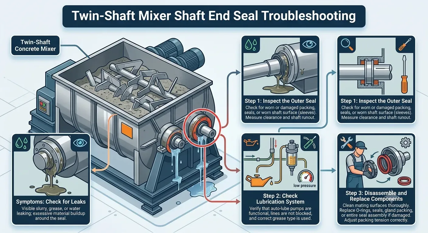
1.1 Symptom: Cement slurry leakage at shaft end housing
Root Cause Analysis
This is the most common twin-shaft mixer seal failure mode, typically triggered by:
- Loss of pressure in automated lubrication system (<1.5–2 bar threshold)
- Progressive grease distributor blockages
- Air entrainment in grease feed lines
- Seal wear beyond axial compensation range
- Improper grease grade selection for wet concrete environments
Once pressure equilibrium is lost, cement slurry migration occurs through micro-clearance gaps in the seal stack.
Diagnostic Protocol
Field engineers should follow this sequence:
- Monitor lubrication pressure under full-load operation (dynamic measurement required)
- Verify cycle completion of progressive grease distributor system
- Inspect seal chamber contamination level (slurry presence = barrier failure confirmation)
- Measure shaft runout (target: ≤0.1–0.2 mm depending on OEM specification)
- Thermal scan of bearing and seal housing during 10–15 minute loaded cycle
Engineering Rectification
- Recalibrate automated lubrication system calibration setpoints
- Flush and re-index progressive grease distribution network
- Replace worn seal cartridges or floating disc assemblies
- Upgrade grease to calcium sulfonate complex or synthetic high-viscosity grade (ISO VG 220+)
- Restore positive pressure differential within seal housing
1.2 Symptom: Severe shaft scoring or abrasive groove formation
Root Cause Analysis
This condition occurs when abrasive cement fines bypass the seal barrier and act as a third-body wear medium. It is frequently associated with:
- Lubrication starvation events
- Seal pressure instability
- Intermittent grease feed failure
- Poor filtration in lubrication lines
This is a direct consequence of uncontrolled cement slurry migration.
Diagnostic Protocol
- Remove seal assembly and inspect shaft wear pattern directionality
- Perform surface hardness mapping across wear zones
- Analyze grease contamination for silica and cement particles
- Review lubrication system pressure history logs
Engineering Rectification
- Install shaft repair sleeve or metallurgical rebuild (HVOF recommended for severe wear)
- Increase grease viscosity grade (ISO VG 220 minimum)
- Add inline filtration for lubrication feed system
- Introduce redundant lubrication line for high-duty mixers
1.3 Symptom: Seal face cracking or catastrophic sudden leakage
Root Cause Analysis
Common in mechanical face seal systems (e.g., BHS-style configurations), this failure is caused by:
- Dry running during startup cycles
- Rapid thermal spikes from frictional contact
- Loss of grease film stability
- Repeated dry batch operation without lubrication recovery time
Once the face seal cracks, leakage becomes immediate and irreversible.
Diagnostic Protocol
- Inspect carbide seal faces for radial cracking or thermal crazing
- Review lubrication system pressure drop history
- Check batch control logic for dry start conditions
- Measure face flatness deviation
Engineering Rectification
- Replace matched seal cartridge set
- Install lubrication low-pressure interlock system
- Modify PLC logic to prevent dry-start operation
- Upgrade grease to high thermal stability synthetic formulation
1.4 Symptom: Elastomer degradation, swelling, or lip seal collapse
Root Cause Analysis
Typical in multi-stage lip seal designs, especially under aggressive washdown cycles:
- Chemical attack from alkaline cement slurry
- Micro-abrasive erosion from fine dust particles
- Thermal hardening due to frictional heating
- Incompatible grease chemistry
Diagnostic Protocol
- Shore hardness comparison (aging vs. new elastomer)
- Visual inspection of lip wear geometry
- Evaluate grease-water emulsification level
- Review washdown frequency vs operational cycles
Engineering Rectification
- Replace elastomer with PTFE-hybrid or chemically resistant compound
- Reduce direct high-pressure wash exposure on seal housing
- Increase grease purge frequency during operation
- Upgrade to labyrinth-style pre-seal protection
2. Lubrication Engineering: Grease Selection for Severe Concrete Environments
Lithium Complex vs Synthetic Polyurea Grease Performance
| Parameter | Lithium Complex Grease | Synthetic Polyurea Grease |
|---|---|---|
| Water Washout Resistance | Moderate, emulsifies under continuous washdown | Excellent resistance to washwater intrusion |
| Mechanical Stability | Good under standard duty cycles | High stability under continuous shear load |
| NLGI Compatibility | NLGI 2 standard | NLGI 1–2 optimized for long feed lines |
| Thermal Resistance | ~160°C limit under oxidation stress | Up to 180–200°C stable performance |
| Seal Barrier Efficiency | Medium resistance to slurry penetration | High resistance to cement slurry migration |
| Compatibility with Progressive Systems | Moderate risk of separation | Low risk of progressive grease distributor blockages |
| Lifecycle Cost | Low initial cost, higher maintenance frequency | Higher initial cost, reduced downtime cost |
| Best Application | Standard batching plants | High-output continuous-duty mixers |
3. OSHA Safety Warning – Mandatory LOTO Procedure
⚠️ LOCK-OUT / TAG-OUT (LOTO) REQUIRED BEFORE MAINTENANCE
Prior to servicing any twin-shaft mixer shaft end seal system:
- Disconnect and lock all electrical power sources
- Fully isolate hydraulic and pneumatic energy systems
- Verify complete mechanical stop of both mixing shafts
- Depressurize lubrication systems before disassembly
- Confirm zero stored kinetic energy in rotating assemblies
Failure to comply with LOTO procedures may result in severe injury, including entanglement, high-pressure grease injection hazards, or unexpected mechanical rotation.
Only trained and authorized industrial maintenance personnel may perform seal replacement or inspection.
4. Engineering Conclusion
Most twin-shaft mixer seal failure cases are not isolated component defects—they are system-level lubrication failures driven by pressure instability, contamination ingress, and improper grease selection.
The key engineering priority is maintaining a stable, pressurized grease barrier that prevents cement slurry migration under all operating conditions, including washdown, dry startup, and high-load mixing cycles.
Proper calibration of automated lubrication system calibration, combined with resistance-optimized grease chemistry, is the decisive factor in extending seal life and preventing shaft damage.
Request Technical Blueprints & Factory Quotes
Submit your machinery parameters below. Connect directly with verified, certified heavy industrial manufacturers to receive custom foundation drawings, layout schematics, and direct-from-factory pricing.